Epistemic Status:  Evergreen - I don’t expect QMK to remove support for this keyboard anytime soon, and if they do, I can always pull up the older commits to keep it running.
Article contains AI generated content
This article contains some code generated with the help of ChatGPT. I’ve noted in the text where it occurs as well as the prompt used.
I’ve been using a mechanical keyboard since around 2014 when I got a kit for the original ErgoDox (with all blank keycaps and Cherry Brown switches) and spent a weekend soldering surface mount diodes by hand, one per key. *I only got one of the diodes backwards and I immediately caught my mistake.
My reason for getting one was entirely related to repetitive strain injury. As a software engineer, I use my hands a lot doing repetitive movements, and I was starting to feel a lot of aches and pains in my right arm in particular. Not wanting it to get worse, I looked around for options and found the ErgoDox. I’ve never regretted my choice and I don’t have the pain anymore. There’s a lot of reasons for that that I could go into in another post.
Then a year or so later I picked up an Infinity ErgoDox as I needed a second one because I was tired of schlepping the other one back and forth to the office. It looks like this:
I made the wrist rests out of some walnut and finished with linseed oil. I really want this keycap set again.
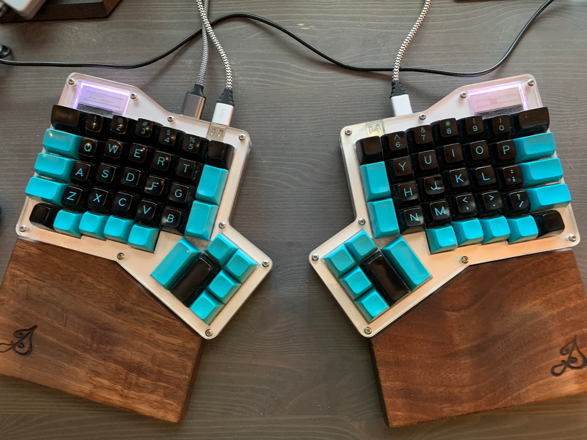
This one also required a little soldering, but only to attach the key switches (also Cherry Browns). It only took me a few hours to do.
As you can see, this one has two LCDs, one on each half. For years I’ve wanted to program them to display images instead of just text, and I finally sat down to do that recently. It was more complicated than I had hoped but hopefully I can document it here and help someone else avoid problems.
QMK Firmware
I haven’t done much hardware or firmware related projects except for these, so I didn’t quite know what I was getting into when I started poking around.
I had already used the QMK keyboard firmware to reconfigure my layout and get them matching on both the original ErgoDox and the Infinity, but I hadn’t updated it in years. Part of this actually started because I had made a change to the Infinity that I hadn’t back-ported to the original and I wanted to get rid of that change because it wasn’t actually working well.
I hadn’t set up the build environment in a long time, so I was happy to find that the project has a shell.nix file, so I tried running nix-shell on it to get a working environment on my NixOS machine. That worked without any problems and so then I started digging into the documentation on how the LCD works.
The ST7565 LCD
This particular LCD seems to come in a few different sizes, but the ones I’m working with here are 128x32 pixels, black and white. There are several functions in the QMK ST7565 library that let you write characters to the display using a provided font, but it wasn’t clear whether you could easily write arbitrary pixels.
The functions st7565_write_char and st7565_write both take char and char * respectively, and write text to the LCD. Further down I found st7565_write_pixel but I didn’t want to have to write my own blitting routine.
Then I found st7565_write_raw_P, which seemed promising. Digging into the source code, I could see it was storing the bytes directly into the buffer being used to drive the display so I wrote some test code and verified that it did indeed take bitmap data and draw it to the display.
Bitmap ordering
One thing I noticed immediately was that the order seemed odd. But I assumed that was just how it was, and tried something pretty obvious, relying on some trivial knowledge I remembered.
The X Window System used to use an image format called X Bitmap or XBM, with a .xbm extension. What I remembered about them was that they were actually C header files. Here’s an example from Wikipedia:
#define test_width 16
#define test_height 7
static unsigned char test_bits[] = {
    0x13, 0x00, 0x15, 0x00, 0x93, 0xcd, 0x55, 0xa5,
    0x93, 0xc5, 0x00, 0x80, 0x00, 0x60
};
These are bitmaps in the original sense of that word, meaning that each pixel in the image is either on or off (black or white) and represented by a single bit. This means that 8 pixels are packed into a single byte.
The way XBM’s work is that the bitmap data is stored in order starting from the top left and going line by line to the bottom right. Inside each byte, the lowest bit comes first. Using the example above we have:
0x13 = 0b00010011 // padded to 8 bits
0x00 = 0b00000000
0x15 = 0b00010101
0x00 = 0b00000000
0x93 = 0b10010011
0xcd = 0b11001101
0x55 = 0b01010101
0xa5 = 0b10100101
0x93 = 0b10010011
0xc5 = 0b11000101
0x00 = 0b00000000
0x80 = 0b10000000
0x00 = 0b00000000
0x60 = 0b01100000
The result looks like this:

Notice how the bit pattern 00010011 got reversed at the top left of the image to make the top of the B and the lowercase L. I thought this might explain the strange output I was seeing when I was setting bytes without having an image to guide me.
The problems became obvious when I created an image to try to display on the screen using some pixel art software called Aseprite. I tried to use this image:
Much thanks to the book “Pixels Forever” for teaching me how to do dithering decently.
Using GIMP, I converted it to an XBM and then copied the binary data out and put it into the firmware. Using st7565_write_raw_P worked perfectly, but what I got came out all garbled. So I did some research and found that the order that the ST7565 expects the bitmap to be in is unusual, at least coming from a graphics programming background that expects pixels to generally go from the top left to the bottom right in linear order.
As I mentioned above, XBM puts the pixels in order from the top left to the bottom right, taking into account the little endianness of the bytes themselves. What the ST7565 does is treat 8 rows of pixels as what it calls a “page” and then within that page, the bytes represent the pixels in the columns starting from the left and going to the right.
So, with the help of ChatGPT I wrote a Python script (using Pillow) to take a PNG from Aseprite and output the data in the right order in a format I could copy into the C code of the firmware1. With some tweaking of my own, I got the script to output the image content in the correct order, with this being the final form of the script:
This is mostly what ChatGPT gave me, which worked on the first try. I’ve made some changes to make it output the “pages” of image content in the right order, as well as the comments.
#!/usr/bin/env python3
import sys

from PIL import Image

PIXEL_ROWS_PER_PAGE = 8

def image_to_c_array(image_path):
    # convert image to black and white
    img = Image.open(image_path).convert("1")
    width, height = img.size

    if width != 128 or height != 32:
        print("The Ergodox Infinity expects a 128x32 pixel bitmap.")
        print(f"The provided image was {width}x{height}")
        sys.exit(1)

    byte_array = []
    current_byte = 0
    bit_index = 0

    pages = height // PIXEL_ROWS_PER_PAGE

    # We'll walk through each "page", outputing a byte per _column_
    # of pixels in that "page".
    for page in range(pages):
        for x in range(width):
            for y in reversed(range(PIXEL_ROWS_PER_PAGE)):
                page_offset = page * PIXEL_ROWS_PER_PAGE
                pixel = img.getpixel((x, page_offset + y))
                bw_pixel = 0 if pixel == 255 else 1
                current_byte |= bw_pixel << (7 - bit_index)
                bit_index += 1
                if bit_index == 8:
                    byte_array.append(current_byte)
                    current_byte = 0
                    bit_index = 0

    if bit_index != 0:
        byte_array.append(current_byte)

    c_array_str = ", ".join(f"0x{byte:02x}" for byte in byte_array)
    return f"static const char image_bits[] PROGMEM = {{{c_array_str}}};"


if __name__ == "__main__":
    image_path = sys.argv[1]
    print(image_to_c_array(image_path))
There was one final wrinkle to getting the images to come out correctly and that’s on line 28 (highlighted above). You’ll notice I’m going through the range in reverse order. That’s because the ST7565 orders the bits in each column from the highest bit to the lowest going down.
As a result, my original code that didn’t have this was still garbled slightly. With that change, the image came out perfectly and then I moved on to my next step.
Animating the LCD
I don’t really have any serious use for the LCDs. One of them I use to display what layer is active, but the other is generally not used. So I wanted to do something fun and make one of them display an animation in a retro pixel art style.
Here’s what I came up with:
The tank is from the NES game Blaster Master, but the rest of the art I made from scratch, again using techniques from “Pixels Forever”.
To do this, I wrote this into my firmware keymap:
#ifdef ST7565_ENABLE

// Layer bitmaps
static const char qwerty_bits[] PROGMEM = /* binary data elided */
static const char symbol_bits[] PROGMEM = /* binary data elided */
static const char media_bits[] PROGMEM = /* binary data elided */

// Animation frame bitmaps
static const char animation_bits[][128 * 32] PROGMEM =
    /* binary data elided */

void st7565_task_user(void) {
    // Index into the array of animation frames
    static int current_frame = 0;
    // Used in the delaying code below
    static int delay         = 0;

    // Move the cursor to the top left
    st7565_set_cursor(0, 0);

    // This is for the mode display on the leader half
    if (is_keyboard_master()) {
        if (IS_LAYER_ON(MDIA)) {
            st7565_write_raw_P(media_bits, 128 * 32);
        } else if (IS_LAYER_ON(SYMB)) {
            st7565_write_raw_P(symbol_bits, 128 * 32);
        } else if (IS_LAYER_ON(BASE)) {
            st7565_write_raw_P(qwerty_bits, 128 * 32);
        }
    } else {
        // this displays the animation on the follower half
        st7565_write_raw_P(animation_bits[current_frame], 128 * 32);

        // Needed to delay a few frames but it ended up only needing
        // to skip one frame, so I could clean this up a bit.
        if (delay < 2) {
            delay++;
        } else {
            delay = 0;
            current_frame++;
        }

        if (current_frame == 8) {
            current_frame = 0;
        }
    }
}

#endif
I’ve added some comments to explain what’s going on some more, but it’s pretty straightforward. I just create a large array of arrays of the bitmap data and then use a frame counter to determine which one needs to be displayed, looping around when it reaches the end.
The whole animation is only 8 frames. The tank itself only needs 4 because of symmetry but I needed the extra frames to add the parallax effect.
I could do this more space efficiently by only writing what needs to change to the buffer, but the library already does some diffing to only change what needs to change on the display, so it might not be worth it.
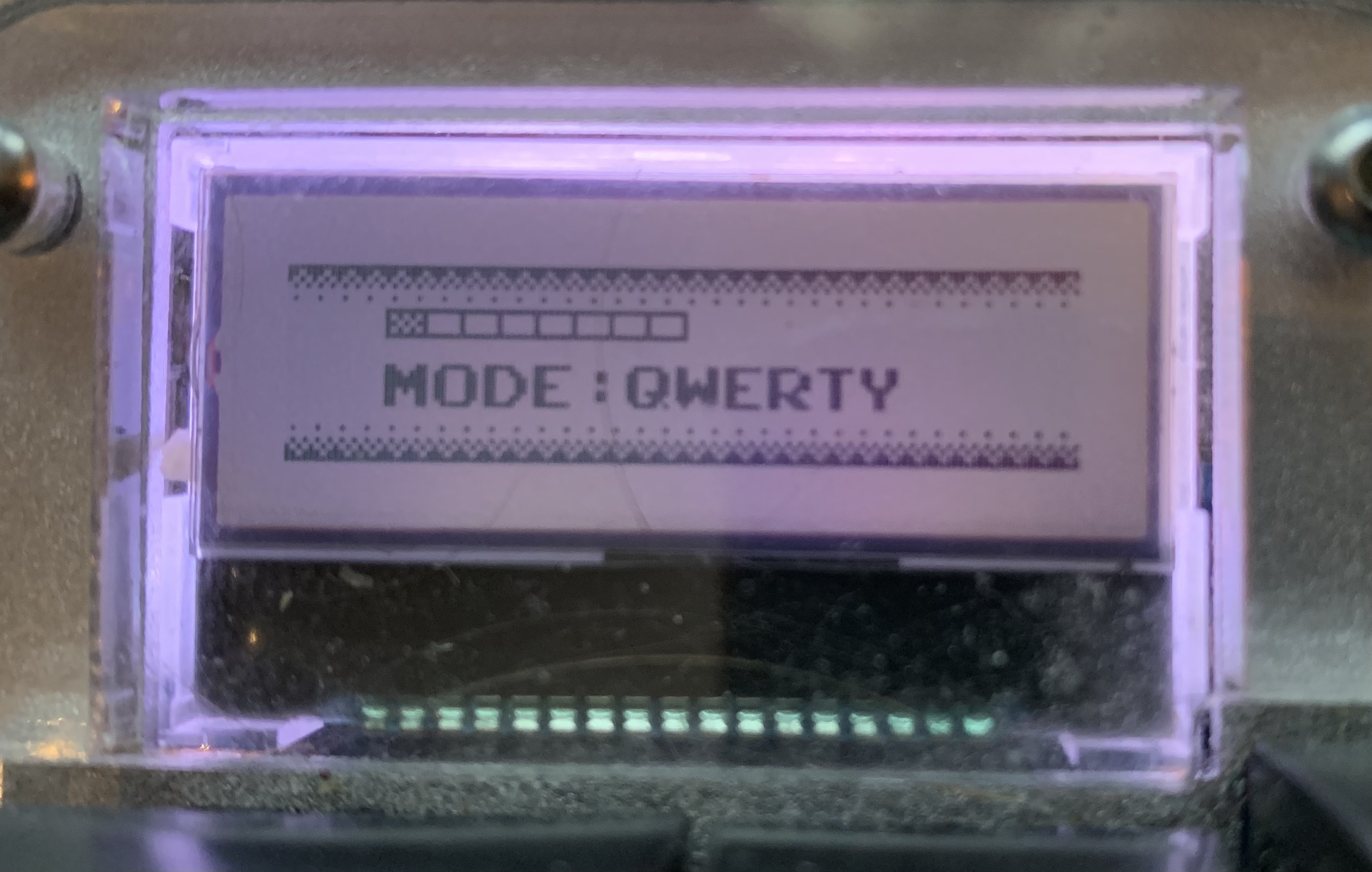
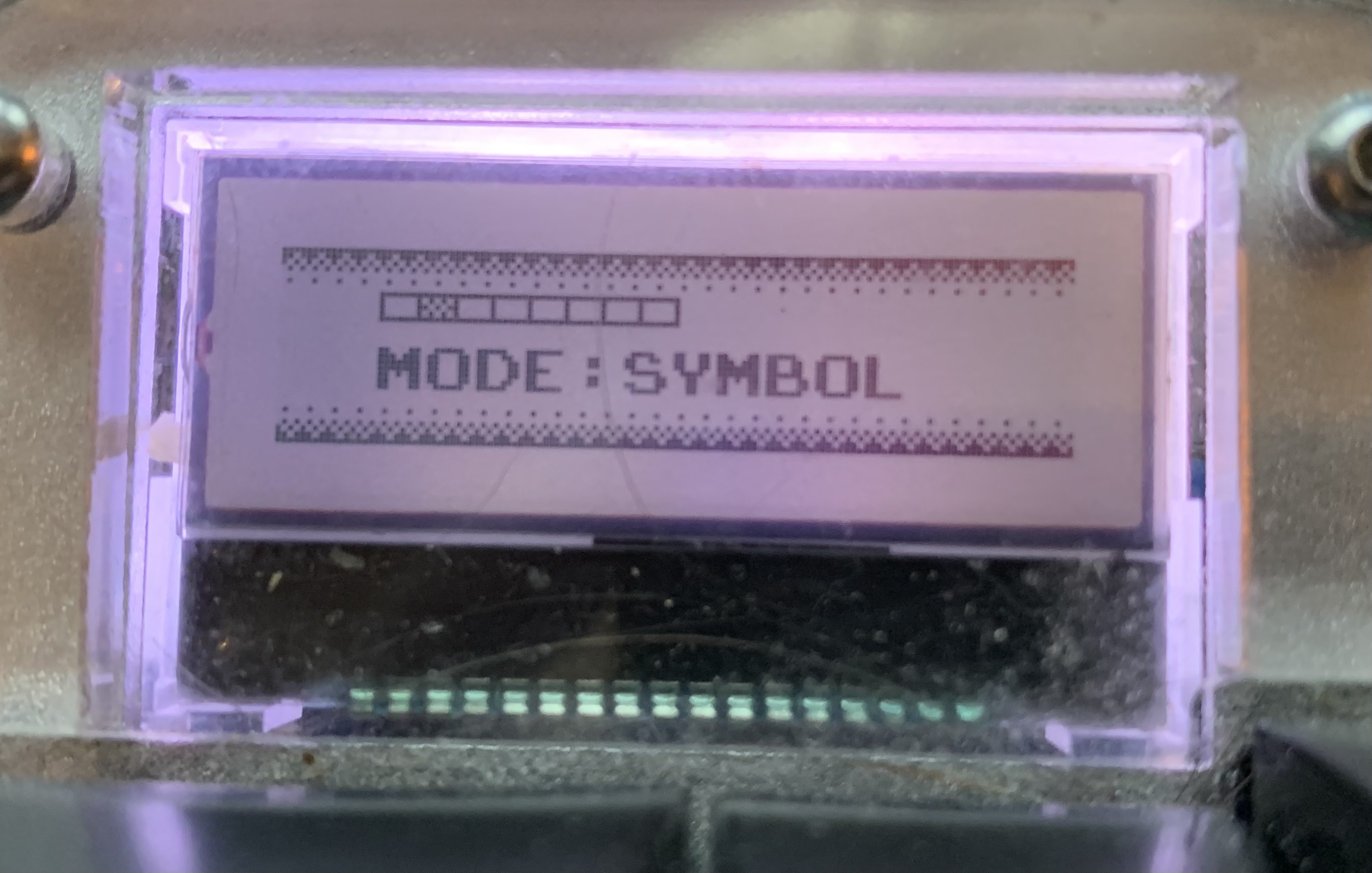
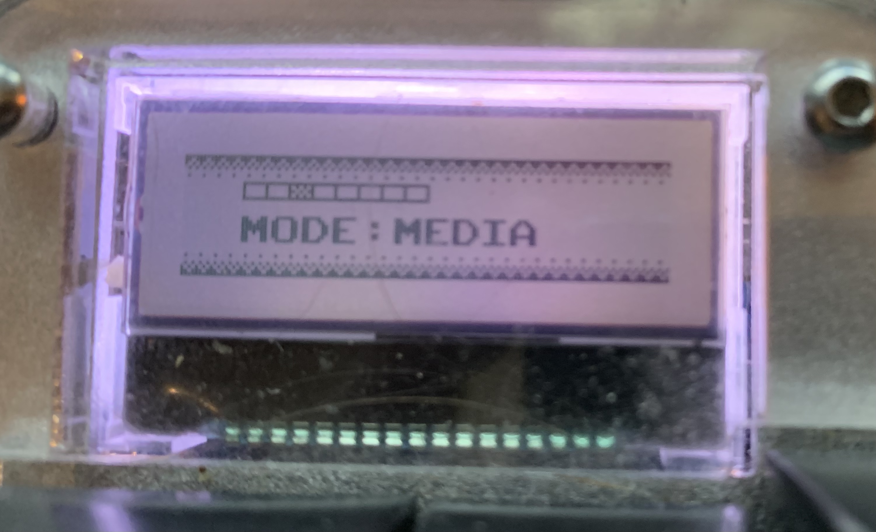
Getting the mode display to work
Then I turned my attention to the mode display that shows what layers are active. On the ErgoDox and many other mechanical keyboards you can have keys that active alternate layers that overlay the previous layers and change keys.
For example, I have a “media” layer that has controls for music and volume that are in the same place as the regular arrow keys.
This really should have been simple
I ran into some trouble getting this to work though.
First, I need to explain something about the Infinity ErgoDox. It’s not one keyboard, it’s actually two. Each half is an independent keyboard and they communicate with each other via a USB cable. One of the halves is the leader and is connected to the computer, while the other one is connected to the leader and is just a follower sending keypresses to the leader2. This is different from the original ErgoDox as it only has one controller for both halves.
Originally I was trying to have the mode display be on the follower, just because it is on the right, but I kept running into trouble getting it to switch what it was showing when the layers changed.
After a lot of head scratching, I finally realized what the problem was. The follower didn’t know what the layer state was because that was controlled by the leader.
Once I swapped which display had the modes and which display had the animation, everything just worked.
I don’t actually have 8 layers configured, I just wanted the boxes to look like a health bar or something from an old game.
Update to the layer tracking issue
It turns out there are
#defines you can add toconfig.hthat will make the leader half communicate layer state to the follower half.Specifically, setting
#define SPLIT_LAYER_STATE_ENABLEwill do the trick.
Future possibilities
One thing I’ve been wondering is if I could change the animation to update whenever a key is pressed, so the tank only moves when I’m typing.
I haven’t configured the LED in the display to change colors with the modes, but that should be simple to add.
I also want to explore other options for the graphics themselves. This was just the first thing that came to mind, probably because I’ve been playing Blaster Master Zero 3 lately.
Footnotes
-
Here’s the prompt I used: “I want to write a Python program to take a PNG image that contains pixels that are either black or white and convert them into a C array of bytes that I can use in the C code for some firmware I’m writing. Can you show me how I can accomplish this?”. I’ve obviously modified the code since this prompt doesn’t ask it to handle the weird pixel ordering. The comments in the code are mine.

-
The source code refers to these as “master” and “slave”. I generally agree with the idea that we shouldn’t use those words in places where they don’t belong. It’s not about “woke” it’s about accuracy. I find things like “primary” and “replica” for databases are just more accurate, and here “leader” and “follower” are more accurate to me.